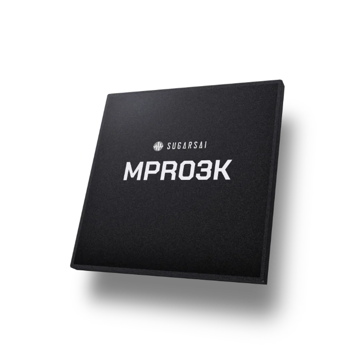
Bridge IC · Receiver
MPR03K
What the sensor sends, at the rate it sends it
MPR03K receives MIPI C-PHY or D-PHY straight from the module under test — up to 4.5 Gbps per D-PHY lane, 18 Gbps across four lanes — and passes the stream to the analysis server over LVDS. At that rate MPR03K carries an 8-megapixel RAW12 stream at 60 frames per second with room to spare.
In production
Introduction
Automotive camera modules have crossed 8 megapixels, and the frame rates they run at keep rising. A bridge board sized for the last module generation cannot keep up with the next — so the test drops resolution, drops frames, or drops the test from the plan. MPR03K sits at exactly that point in the line. MPR03K is an ASIC, not licensed PHY IP on programmable logic, and its analog front end — the input circuits that receive the signal off the wire — is designed in-house. That is why the figure holds across the cable from the test socket to MPR03K, and why it keeps holding on a board that runs around the clock.
2.8–3.2 Gsps
C-PHY per lane (19.2–21.9 Gbps across 3 lanes)
4.5 Gbps
D-PHY per lane (18 Gbps across 4 lanes)
15 dB
two-stage CTLE high-frequency boost
Key Features
What makes MPR03K different
Signal path
MPR03K is the receiver. MIPI C-PHY (three lanes) or D-PHY (four data lanes and a clock) in; LVDS out to the analysis server. Nothing is decoded in between, and nothing is stepped down to fit the link.
Analog blocks
Three analog circuits do the work that logic cannot: a full-rate glitch remover, a two-stage continuous-time equalizer with up to 15 dB of high-frequency boost (peaking) against cable loss at the frequency stated in the datasheet, and clock and data recovery (CDR) that retimes the stream and deskews the lanes without buffering a frame. The glitch remover is covered by a granted patent.
Measured after the cable
A receiver figure here is measured the way the part will be used — after the cable used in the equipment, not the span the interface specification assumes.
Design ownership and status
The MIPI PHY and the analog front end are SUGARS AI's own — no third-party PHY IP, and no per-unit royalty on the interface. MPR03K is packaged in a 289-ball flip-chip CSP and is available now.
Specifications
MPR03K at a glance
Function
MIPI C/D PHY → LVDS (receiver)
Input
C-PHY 3 lanes (A, B, C trio per lane) · D-PHY 4 data lanes + 1 clock lane
Output
LVDS
C-PHY
Max 2.8–3.2 Gsps per lane (19.2–21.9 Gbps across 3 lanes)
D-PHY
Max 4.5 Gbps per lane (18 Gbps across 4 lanes)
Measurement basis
After the cable used in the equipment
Package
Flip-chip CSP, 289 balls
Status
In production
Applications
Where it is used
Automotive camera module test
End-of-line
Mobile camera module test
SoC emulation and verification systems
For further details and datasheets,
contact sugars@sugars.kr
Datasheets, evaluation boards, and engineering samples are available on request.